The buttons, sliders and tick boxes let you:
- Define a set of engine parameters
- Start and stop the animation or rotate to a particular position. If “stop TDC”is ticked, the animation stops at each Top Dead Centre.
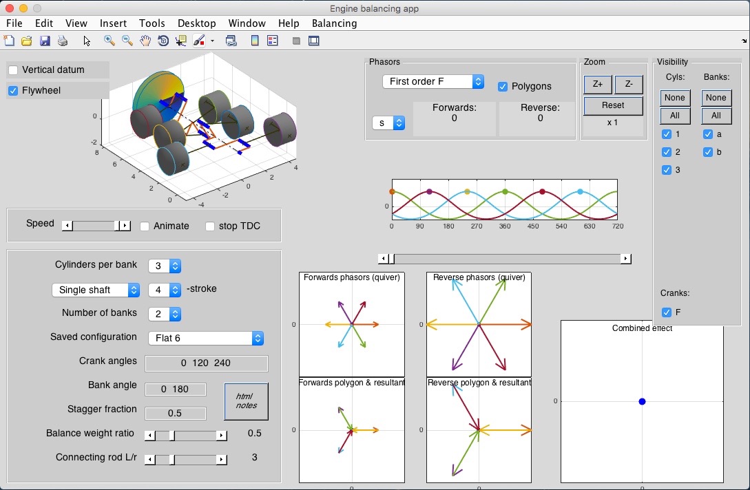
- Pick forces or moments, first or second order for the phasor graphs.
- Pick position (s), velocity (v) or acceleration (a) for the piston motion graph. For a 4-stroke engine, the dots show the rotation in which the cylinder fires and you can judge whether the firing intervals are uniform or uneven.
- Zoom in or out on the phasor diagrams. They zoom together so phasors are to scale on all 5 graphs.
- Pick which cylinder numbers (inline) and which bank numbers are displayed in the phasor diagrams. Choose whether to display the vector polygons or just the resultant in the lower two graphs.
You can set up an engine “from scratch” by picking numbers of cylinders etc or you can pick a saved style using the “Balancing” menu. “Browse database” brings up a list:
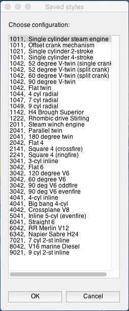
The initial number here is CHSB = [inline_cylinders, kind_of_H_engine, 1/2/4 stroke, banks]
Most engines have a single crankshaft (H=0) but, historically, there have been some very significant “H-engines” with two crankshafts.
- H=1 defines a contra-rotating second crankshaft as a reflection of the first
- H=2 defines a contra-rotating second crankshaft folded (rotated about x-axis) to point backwards
- H=3 defines both crankshafts rotating in the same direction, with the second phase-shifted by 180 degrees.
Preset and automatic styles:
- If you set up an engine using the controls on the window (instead of using the “Browse database” menu) the program will search the database for all engines having the required CHSB combination and display the first of these. All the relevant styles will be listed in the “Saved configuration” popup (so with 3,0,4,2 you would get the five configurations shown in the style database window above). If no configuration is found, the program will generate a default one, “Auto”. This tries to be sensible but may not be the best possible.
- If you alter the crank angles, bank angles or split angle the configuration is deemed to be a different engine and a new style, “Custom” will be added to the end of the list. This is not saved when you exit the program and is simply the edited version of whichever style you last altered. Changes to other parameters (connecting rod length, balance weights etc) do not trigger the Custom style.
- If you want to save a new or altered configuration, use the “List in cmd window” menu. This will write out the current settings in the command window. You can then paste them into style_database.m. Look carefully to see how the code works!
The “Expand axes” menu will reposition the axes so any one of them is much larger, e.g.:
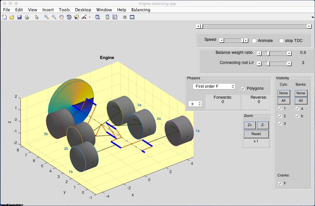
I have added piston numbers 1a, 1b, 2a... to this image to illustrate the cylinder and bank numbering scheme. Note the orientation of the x,y,z axes: the crankshaft is inline with the y-axis.
Some engine parameters are not visible in the main window. You can edit these using the “Edit variables” menu
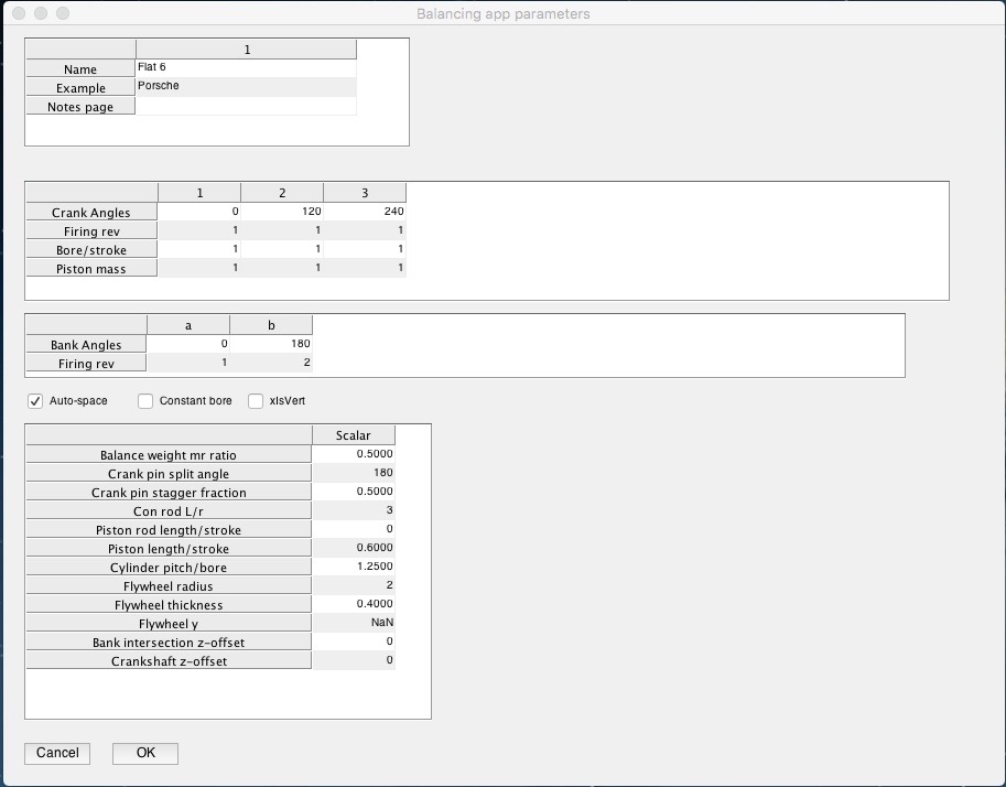
All the calculations assume a crank radius (stroke/2) = 1 and a rotational speed of omega = 1 radian/second. This cannot be set (no point!). You can however set a piston mass, for instance to investigate a triple expansion steam engine where some pistons are heavier than others.
- "Crank angles” are the angles shown as theta in the notes. I tend to define one crank as having theta=0 but this isn’t essential.
- “Bank angles” define the orientation of each bank of cylinders in a V-, flat or radial engine. This is angle phi in the notes.
- In a 4-stroke engine, cylinders where Firing_rev(inline) + Firing_rev(bank)+crankshaft_number is EVEN fire on one revolution and those where it adds to an ODD number fire on the alternate revolution.
- If Auto-space is ticked, the y-spacing is calculated from the bore and pitch/bore parameters. If unticked you can specify a y-value for each cylinder in bank 1.
- xIsVert changes the display to make the engine and phasors draw with the x-axis vertical.
- The “balance weight ratio” = 1 when the balance weight (mr) exactly cancels out the forwards-rotating force phasor for each piston. Hence mr(balance weights) = (weight ratio) * 0.5 (sum of mr for all pistons on this crank pin)
- For engines with more than one bank of cylinders, split angle defines the increment in each crank angle theta from one bank to the next. A flat 6 engine (as above) therefore needs split angle = 180 degrees.
- With more than one bank of cylinders, the connecting rods may all lie in the same plane (e.g. one can have a forked big end, or one “master rod” providing a number of separate “pseudo-big-ends” for the others). This would be with “stagger fraction” = 0. Other engines, especially those with some split angle, will need the banks to be staggered along the crankshaft. Each bank is incremented in the y-direction by (stagger fraction) x (cylinder spacing) relative to the previous bank.
- Steam engines and large 2-stroke Diesels tend to have a connecting rod - crosshead - piston rod - piston configuration. You can define the length of the piston rod and the thickness of the piston.
- You can specify a flywheel position (see the steam winch style); NaN will auto-position it on the end of the crankshaft.
- The bank intersection line can be shifted above or below the y-axis by setting a z-offset, as can the crankshaft itself. This is needed for creating H-engines; see also the Rhombic drive.
The rest should be self-explanatory. If you cannot see a resultant phasor, it is probably because the components sum to zero. It may help to zoom in and out and/or turn off phasor visibility, stop at each Top Dead Centre and turn on the phasor for that piston so you can see the diagram "building up” as it would on paper.
nb. There are n! ways of drawing a vector polygon of n phasors. The program draws all banks (cylinder 1), all banks (cylinder 2) etc. The resultant will be the same regardless of the order used when drawing the diagram.
How does this relate to answering questions that require a calculation?
Draw a pair of phasor star diagrams (forwards and reverse) like the top two graphs, showing angles and lengths (as a multiple of mrw2).
- Remember if drawing moments that a moment (= “torque" or “couple”) is defined as a vector perpendicular to both the force vector and a vector defining the y-offset of this cylinder from some arbitrary datum, i.e. a cross product T = r x F. The app uses the mean piston y-value as this datum; this means that engines such as a single cylinder or parallel twin show no moment despite having unbalanced forces. You need to define your axis when calculating moments.
- Remember your basic mechanics too: if the forces on a planar object are in equilibrium, the moment exerted on is independent of your choice of datum axis (perpendicular to the plane). If the forces are not in equilibrium, the moment may calculate as zero or not, depending on your choice of axis. (This is why rockets need to carefully adjust the direction of the rocket motor to keep the line of action of the resultant force passing through the centre of mass, otherwise the rocket will veer off to one side and turn into a Catherine wheel).
It may be obvious from the star diagrams that the phasors cancel out.
If not, draw a pair of phasor polygons. Where possible, draw together any pairs of phasors that will cancel out. Write the remainder as [i, j] vectors and add them up to get the resultant as an [i j] vector. This can be converted to magnitude and angle (for both the forwards and reverse cases).
The combined effect will be an ellipse with major axis = sum of magnitudes, minor axis = difference in magnitudes. You need to identify whether the resultant effect at a moment in time travels around the ellipse in the engine rotation direction or the reverse direction. This will depend on which magnitude is largest, the forwards or (typically) the reverse resultant.
Note that these ellipses are for just one component (first or second order, force or moment). The overall effect (sum of these) is not (currently) shown in the app.