This app illustrates how the forces would add if we had a pair of contra-rotating shafts, each carrying an off-axis mass.
This isn't a very common situation, though some machines do actually use shafts rotating in opposite directions, e.g. the propellers on the Fairey Gannet:
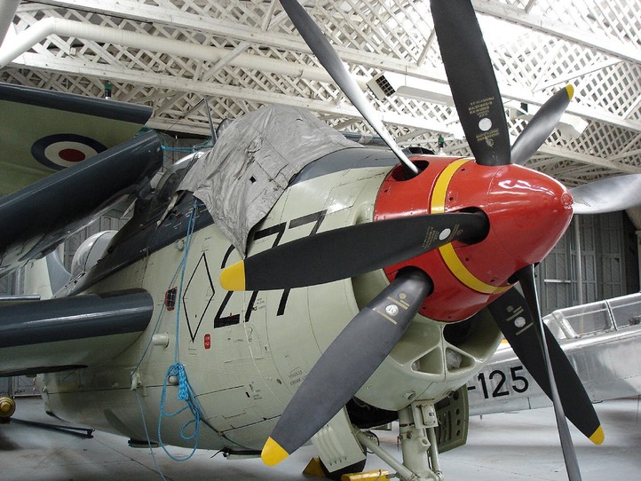
(Wikipedia image)
(the inertia and gyroscopic effects of a single large propeller can prove quite tricky for pilots - using two also provides some increase in propulsive efficiency, since it can avoid the kinetic energy that is wasted in the swirling flow from a single propeller).
The real interest in this case is that it is a mathematical model for the forces generated by a reciprocating mass, e.g. a piston in an engine. Just like an "equivalent circuit" in electronics, it leads on to a much easier way of doing the force and moment calculations i.e representing them by a vector diagram (which rotates but does not change shape, it is time-invariant) rather than trying to add a number of out-of-phase cosine waves for forces that are continually varying.
The long_balance and fr_masses apps form an introduction to balancing_app which combines both concepts to show how piston engines are actually balanced.
Let's start by running the app (in Matlab, choose the right folder, type fr_masses).
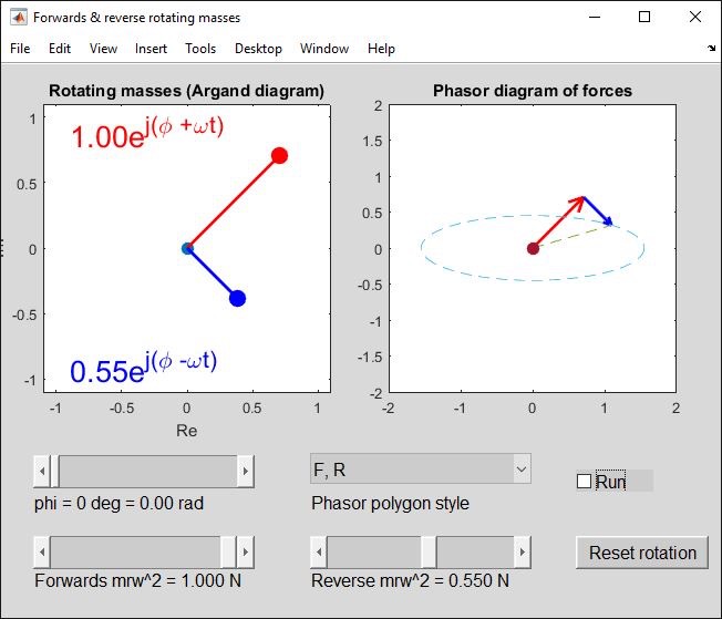
The red mass rotates anti-clockwise (positive omega following the usual convention); blue rotates clockwise. These are the "forwards" and "reverse" directions. Click “Run” to animate it.
The position of each mass is shown as a complex number on the Argand diagram. This lends a bit of mathematical rigour - don’t worry about it, you do not actually need to use complex numbers unless you want to follow a completely algebraic approach. At an instant in time, each force is simply a vector and we will end up adding vectors using basic trigonometry etc - but it does allow a complete mathematical definition (given on the formula sheet in exams) as well as the representation by way of diagrams.
Anyway, start the app and click on "Run". The masses will start to rotate around the axis; the vector diagram shows how the two force vectors add to give to resultant force that varies in time and direction. With the initial force setting (forwards 1 N, reverse 0 N) the resultant follows the forwards mass and rotates anti-clockwise; with (0,1) it follows the reverse mass and rotates clockwise.
We can represent a 2D vector as a complex number on an Argand diagram (left diagram, real and imaginary axes). ejtheta lies on a unit circle (i.e. radius = 1) at an angle theta from the real axis. Hence ejwt (i.e. theta = wt) is a vector that rotates anti-clockwise at w radians/second; e-jwt rotates in the opposite direction.
People sometimes wonder how an imaginary number can be any use in modelling a physical situation. All we are doing, however, is defining the real part of a complex number as the horizontal component of a vector and the imaginary part as the vertical component. The complex number representation is useful because it gives us a way of writing vectors that rotate. I call these "phasors" as a reminder that they are actually rotating.
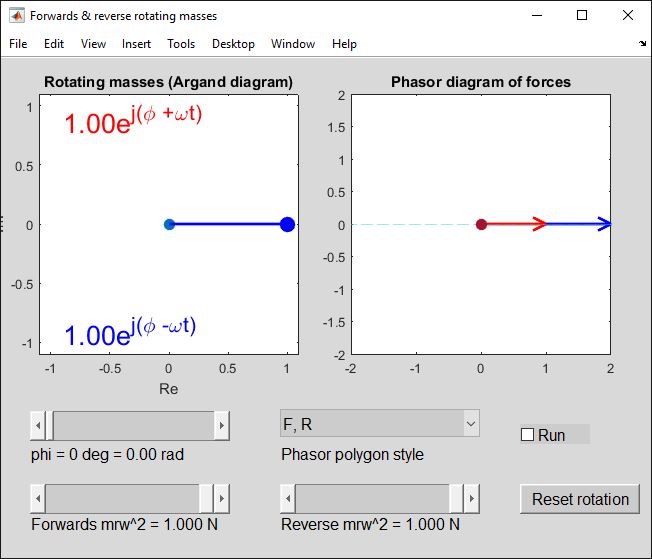
With equal forces, (1,1), the horizontal components add and the vertical components cancel out. The resultant force is then always in the horizontal direction, ejwt + e-jwt = 2 coswt (animate it and check!).
Now lets add some angle phi to both expressions
ej(phi+wt) + ej(phi-wt) = ejphi(2 coswt).
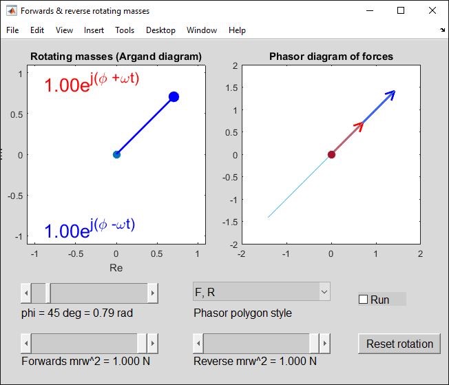
ejphi is constant, e.g. ejpi/4 = (1+j)/sqrt(2); the 2 coswt multiplier makes the net force oscillate along a line at this angle. Actually all that has happened is we have rotated both diagrams by 45 degrees anti-clockwise.
Now, returning to the phi = 0 case, try a pair of different forces, perhaps (1, 0.5)
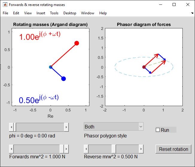
As before, the horizontal components add. The vertical components do not completely cancel, so we are left with some vertical force - the locus of the resultant throughout a rotation is an ellipse (part-way between the circle and line). Since 1>0.5, the forwards-rotating component "wins" and the resultant move anti-clockwise around the locus when we animate it.
Note that when we add vectors, we must draw them "nose to tail" but it does not matter which vector comes first. The app will draw them as "F then R", "R then F" or, as above, both at once to give a vector parallelogram.
Why is this useful?
Suppose we have single cylinder engine (n.b. a multi-cylinder engine is just like a number of single cylinders, we will expand the method later).
We have some components (crankshaft, the big-end of each connecting rod) that either actually rotate or move in a circular path - it makes no difference - and we can balance them using shaft balance theory (the long_balance app).
Other parts (the piston, gudgeon pin and little end of the connecting rod) move in a straight line with position rcoswt, velocity -wrsinwt, acceleration -w2rcoswt, where r is the radius from the crankshaft axis to the big-end. (Remember the engine's "stroke", the distance the piston moves between top and bottom dead centre = 2r).
If the crankshaft is balanced as a shaft and I then add a piston, we will get a reciprocating force, F = -mw2rcoswt. (This is assuming a "long" connecting rod so the motion is close to sinusoidal - with a short connecting rod we can add extra 2w, 4w terms to improve the model).
It is often better to add a balance weight to the crankshaft, opposite the crank pin, that will generate a force opposing the "forwards" mass in our forwards&reverse mass model. This takes us from the
mrw2(ejwt + e-jwt)/2 force (horizontal shaking) to a mrw2(e-jwt)/2 force (constant amplitude, half the previous peak force, but varying in direction).
To cancel out this remaining component we would need either an actual balance weight on a contra-rotating shaft or (more usually) other pistons whose contra-rotating force terms would combine to cancel each other out.
The next app, "balancing_app", shows how we can draw separate diagrams for forwards rotating and reverse rotating phasors in a multi-cylinder engine. Ideally we want the reverse rotating phasor diagrams (forces and moments) to be closed polygons, so that there is no need to design and build a gear-driven balancer shaft rotating in the opposite direction to the crankshaft. This is usually possible -but not always.
For an inline multi-cylinder engine, the forwards diagram mimics the crankshaft angles (easy!) and the reverse diagram is its mirror image, so the forwards case balances automatically if the reverse one is OK. For V-engines, the forwards diagram tends to have an imbalance that is easily corrected by adding balance weights to the crankshaft.