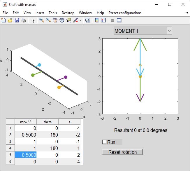
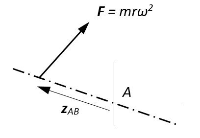
Long_balance shows a rotating shaft with one or more unbalanced masses hanging off it. Each mass follows a circular path because of a centripetal force mrw^2; an equal and opposite force (Newton's third law) therefore pulls outwards on the shaft.
You can enter values for mrw^2, the angular orientation theta and the axial position z for up to 6 masses. Negative mrw^2 values can be used to model a hole in a solid disk (mass symbol is then a circle instead of a solid blob).
Note: the rotational speed omega affects the magnitude of the forces but cancels out in the equations. I could equally well have drawn vectors of mr instead of force and mr^deltaz instead of moment. Force balance requires that the centre of mass lies on the shaft centreline; moment balance requires that one of the "principal axes of inertia" is coincident with the shaft centreline. If you were doing physics, you would learn that rigid objects have 3 orthogonal (=at right angles) principal axes: an object can spin freely about any one of these without needing an applied torque to maintain the axis alignment.
This gets complicated, which is why I have used force vectors - much easier to describe!
The popup menu sets the vector display to show either force ("short balance") or moment ("long balance") - moments 1 to 6 are defined about the axial position for rows 1 to 6 in the input table.
What to do with it?
When answering a shaft balancing question, you need to satisfy 4 conditions:
- Net force = 0 both horizontally and vertically
- Net moment = 0 about both a horizontal and a vertical axis
Note that this is equivalent to the condition:
- Net moment = 0 about both a horizontal and a vertical axis through point A
- Net moment = 0 about both a horizontal and a vertical axis through some other point B
This is because if there is zero net force, the net moment is a constant everywhere: conversely if we make the moment constant everywhere (=0 in this case), the forces are automatically balanced too.
Generally speaking these conditions can be met by adding a pair of masses to the shaft. For each mass one must choose an axial position (z) - the required (mr) and angle theta can then be calculated. These two (mr, theta) pairs give one the necessary 4 degrees of freedom to satisfy the 4 conditions.
- Start with a simple moment calculation.
Let’s take a pair of masses (the preset “2 at 180” case) that have force balance but not moment balance.
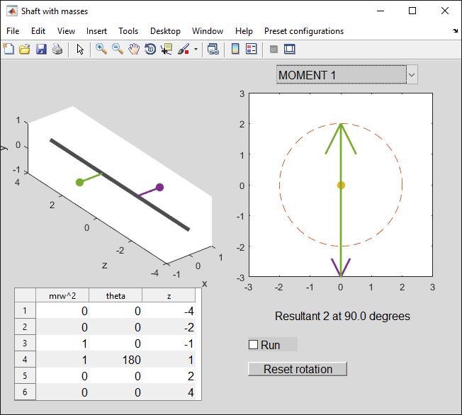
“Moment 1” is the moment about the z-value corresponding to row 1 in the table (z = -4). The mass at z = -1 is pulling with a force mrw^2 = 1N so it exerts a moment of magnitude 1*(-1 - (-4)) = 3 Nm. At this moment in time, the moment vector points downwards (think about the right-hand rule) - spot the arrow tip at -3.
The mass at z = +1 generates a moment of 1*(1-(-4)) = 5 Nm. This is the green arrow on the diagram, pointing upwards from -3 to +2 (it overlays most of the previous arrow, which is why only the tip was visible). The net force (easily added since the moment vectors are parallel) is 5-3 = 2 Nm. (We can also see this by taking moments about z = -1. Only the force at z = 1 contributes to this moment).
Click on “Run” and the shaft and vector diagrams will rotate.
Mathematically the moment acting through some point A due to a force vector F is defined as M = zAB ^ F. zAB is a vector from A to any point on the line of action of force F; in our case, the forces act perpendicular to the shaft so we can simply use the axial spacing (difference between z values in the table). The cross product defines the moment vector direction (perpendicular to both zAB and F).
Knowing that with zero net force the moment should be constant about any point, we expect “Moment 2’, ‘Moment 3” etc to all be the same. Use the popup menu to see if this is the case.
OK, we can see what the diagrams mean. Let’s try adding masses to the table to reduce the force and moment imbalances to zero.
The most obvious solution would be to cancel out the effect of each mass by putting another mass opposite it:
Note: since we are adding a pair of masses that have force balance, we can put them at any axial position - only the spacing between them matters. So for instance, if we slide the two new masses +3 in the z direction we get:
(You can rotate the 3D view if you click on the rotation icon ![]() on the tool bar, then hold down a mouse button and drag the shaft view).
on the tool bar, then hold down a mouse button and drag the shaft view).
We can spot that this configuration is bound to have zero net moment because it is symmetrical about the z = 1.5 point.
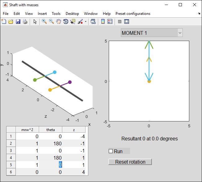
Given though that we want to generate a moment rather than a force, we have the nicer option of using lighter masses with a bigger spacing between them. Without much calculation, we can see that to achieve moment balance we need to add a pair of masses with 180 degree spacing (so as not to upset the force balance) but providing a moment that cancels the 2 Nm.
Let's try masses at z = -2, +2 (spacing 4 m). Taking moments about z=-2, the force at z=2 must be 2 Nm/4 m = 0.5 N. The masses are all "in plane" so we don't need to do an angle calculation - just make them oppose the original moment. We then get:
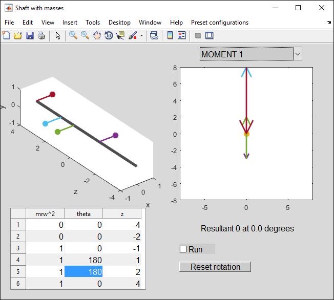
We could increase the spacing and use smaller masses, e.g. doubling the spacing from 4 m to 8 m requires the forces to halve, from 0.5 N to 0.25 N:
So far the forces have all been in the same plane - we hardly need a vector diagram. Now let’s move on to cases where the forces are non-planar.
There are two possible approaches:
- Define moment vectors (perpendicular to the force direction) and add these vectors
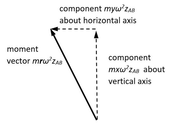
- Alternatively, define scalar moments about a defined axis (e.g. horizontal or vertical) and add these. Do this twice, once for each axis. (All we are doing here is taking components of the moment vector!).
It may help to think about how the components of a force vector generate the components of a moment vector. A mass m at some radius r from a rotating shaft axis generates a force vector:
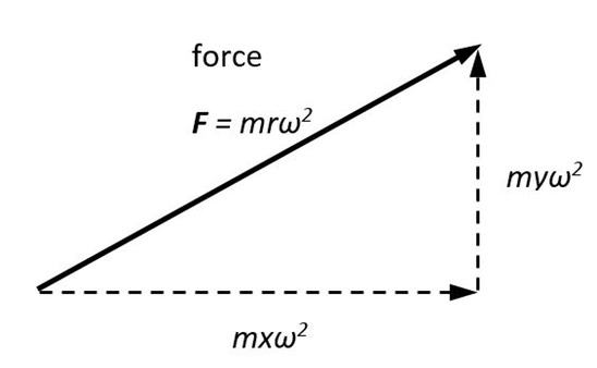
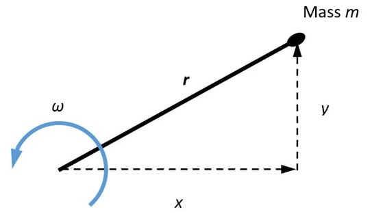
The line of action of this force is at some distance z from the point A at which we have chosen to calculate a moment:
Thinking back to A-level mechanics, a good approach (avoiding simultaneous equations) to a problem with 2 unknown forces is to take moments about a point through which one of the forces must act. Let's call this point "A". FA generates no moment about A so disappears from the equation - we than have an equation for the other force, FB.
To find the second force, we can either repeat the procedure (take moments about point B to find FA) or sum the forces and add a mass to cancel them out.
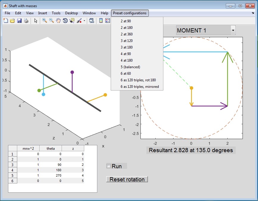
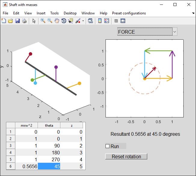
Let's take the initial setup as an example (preset “4 at 90”).
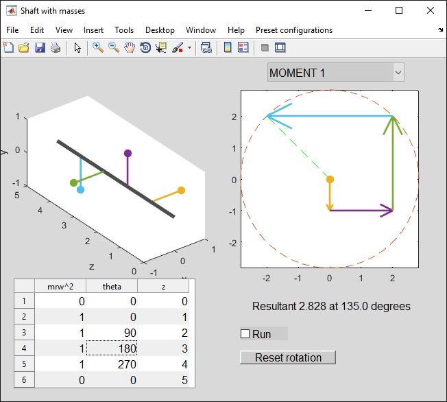
Taking moments about point "1" (z = 0) due to the four masses, with unit vectors (I,j) defined relative to the initial shaft position so that theta=0 defines the I direction:
M = -(1*1)j + (1*2)I + (1*3)j - (1*4)j = -2i + 2j Nm
This is equivalent to the "Resultant = 2.828 at 135 degrees" output from the app.
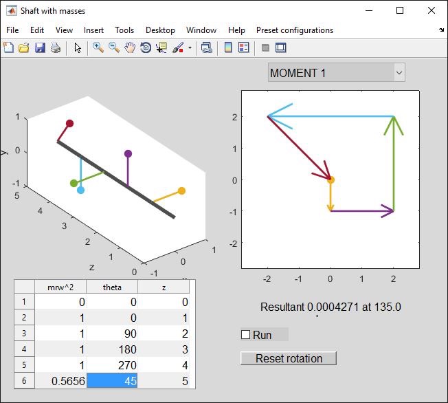
Now let's suppose we want to cancel out this moment by adding a mass at position "6" (z=5); remember we are taking moments about the z=0 position.
In terms of magnitude, we need (mrw2) * (5-0) = 2.828 hence mrw2 = 0.5656 N. The applied force must be 90 degrees around from the moment direction so the mass needs adding at 135-90 = 45 45 degrees (think about the moment vector direction - satisfy yourself why it is not 135+90 = 225).
Hey, that's worked!
I could now repeat the procedure, perhaps taking moments about position "6", to find the mass needed at point 1. In some ways this is nice because even if I got the mass 6 wrong, it drops out of the equation and I stand a good chance of getting mass 1 right.
It is much easier though, having found one mass, to just use a force balance to determine the other (screenshot). The net imbalanced force is now 0.5656 N at 45 degrees:
so we will add 0.5656 N at -135 degrees:
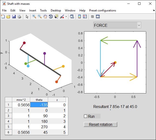
That's done it! (You might like to check Moment 1 again and satisfy yourself it is unchanged - this is why I added the second mass at z=0, not anywhere else).
More advanced things to try:
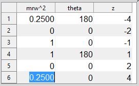
- Look at a disk with a hole balanced by a couple of stuck-on weights:
Spot the hole (negative mass).
- We started with a force-balanced pair of masses. Following on from this, let's think about how we can arrange a set of masses such that they are automatically balanced in terms of force and moments. Remembering that if a subset of the masses (2 or 3 of them, maybe) have force balance, we can then just add the moments due to each group.
First consider 6 masses at 60 degrees (preset). Clearly the forces balance:
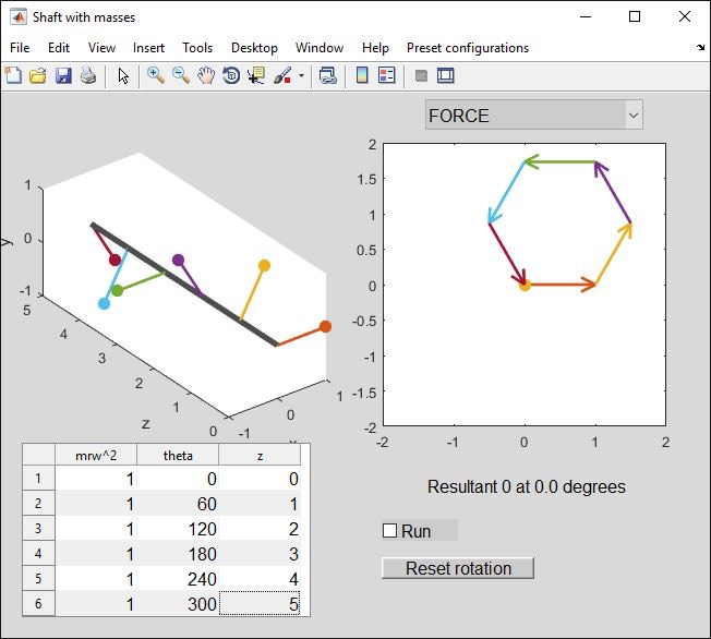
You might expect the moments to balance, but they do not:
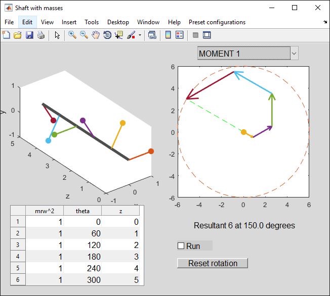
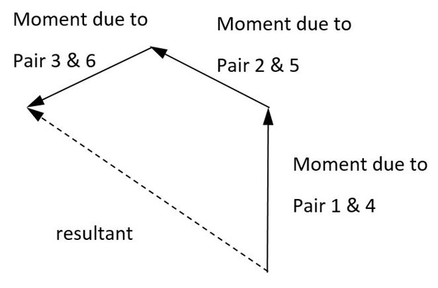
Let's imagine masses 1 & 4 to be a force-balanced pair, similarly 2&5, 3&6. Each generates a moment (constant everywhere because the pair is force-balanced); these are equal in magnitude but not direction.
With mass 1 at 0 degrees, these three moment vectors will be at 90, 150, 210 degrees (i.e. they clock around at 60 degree intervals). If they were at 120 degree intervals, the vectors would close (zero resultant) - an equilateral triangle - but at 60 degree intervals, they don't.
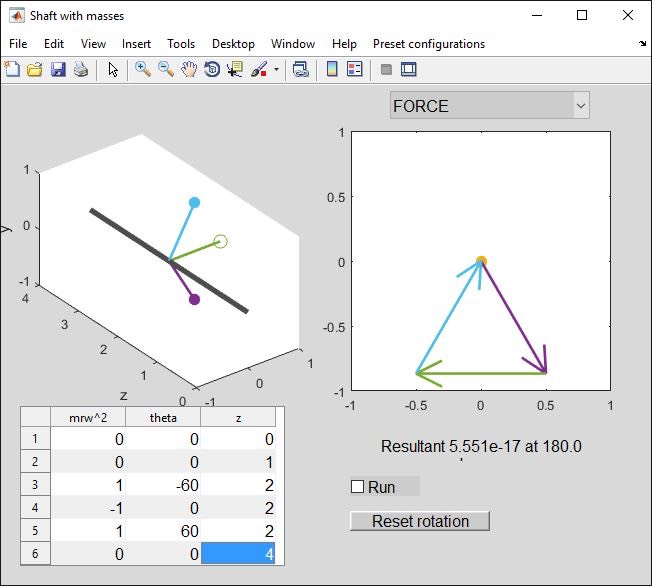
So, let's change the arrangement - take these pairs and clock them around at 120 degree intervals (preset “6 as 120 triples, rot 180"):
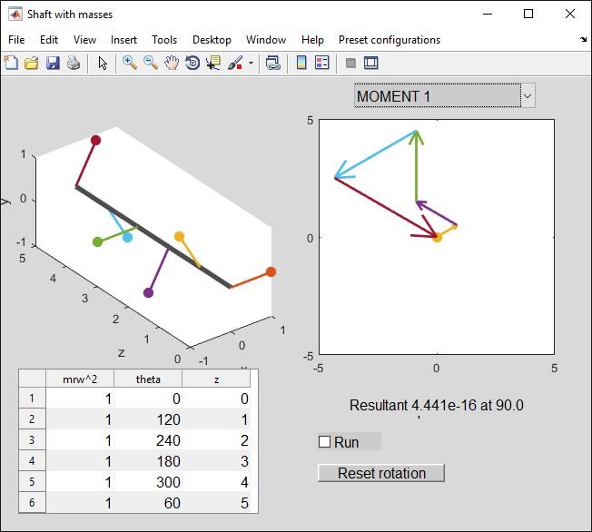
That works! The point of the vector diagrams, as opposed to solving a set of equations with five unknown angles, is that they are much simpler and give you some intuition about sensible arrangements.
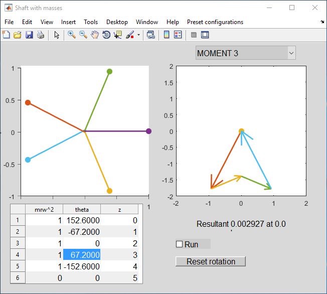
Finally, let’s try one where we use components of the force and moment vectors (about horizontal and vertical axes) rather than a vector sum. Load the “5 (balance)” preset. I have rotated the shaft so you are seeing it end-on:
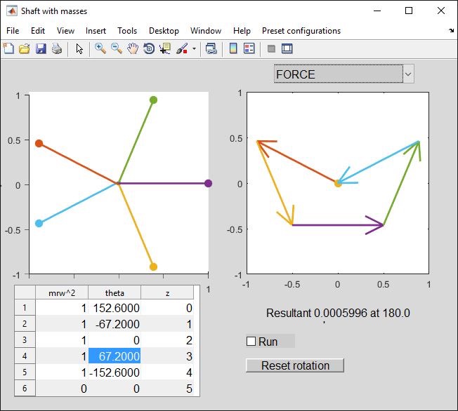
Note that, in the left-hand diagram above, masses have rotational symmetry about a horizontal axis through the central mass (x-axis, not the shaft axis!). I am not bothering with complete vectors because I can immediately see that (a) the vertical components of force will cancel out (masses 2&4, 1&5 have equal but opposite y-coordinates), (b) moments about a vertical axis will cancel out (2&4 are equi-spaced about 3 with same x-coordinate, ditto 1 &5).
Now suppose we don’t know one of the pairs of angles and need to find it. Suppose only the 67.2 degrees is given so we have:
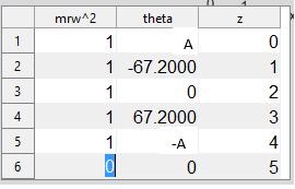
Satisfy yourself that the equation for horizontal force components to sum to zero is:
1 + 2 cos 67.2 + 2 cosA = 0
Use your calculator to find A. (Note, I am pairing 67.2 and -67.2, A and -A because cos is an even function). OK?
Now think of the moments about a horizontal axis (we know from the symmetry that they are already zero about a vertical axis).
Look back to the explanation above where the moment component about a horizontal axis is myw2zAB. Satisfy yourself that the equation to be solved is 2(sin67.2 - 2sinA) = 0, then use your calculator to solve for A. Like all trigonometric equations, this gives you two possible answers - we know from the force calculation above that we want the “second quadrant” one, i.e. >90 degrees.
If you really want to know how I found the 67.2 degrees (unlikely to be asked this), click here.